
BCD to Seven Segment Display Manufacturer,Supplier and Exporter in India

Product Code : EL-DET-1527
Jlab Export is a leading BCD to Seven Segment Display Manufacturer,and suppliers in India
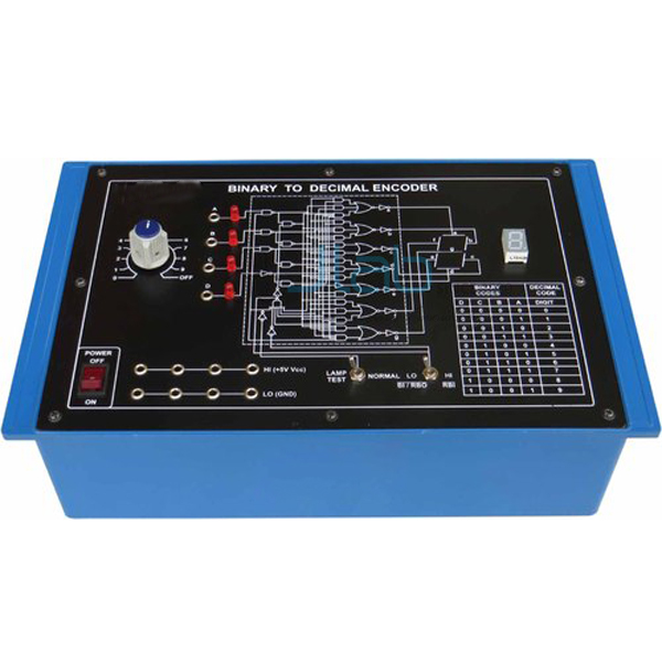
BCD to Seven Segment Display (code EL-DET-1527) is a digital electronics trainer kit that shows how a binary coded decimal (BCD) input is decoded to light a digit on a seven segment display. Four SPDT switches set the inputs A, B, C and D, and a built-in decoder driver IC drives the display panel. It is made by Jain Laboratory Instruments Pvt Ltd (JLab) at its works in Ambala, India.
Specifications
| Parameter | Detail |
|---|---|
| Object | To demonstrate the working of a BCD to seven segment display |
| Display | Seven segment display, common anode, LED type (built in) |
| Decoder driver | BCD to seven segment decoder driver IC (built in) |
| Logic inputs | Four SPDT switches for the variables A, B, C and D, giving logic 1 and logic 0 inputs |
| Input forms | Changing a switch position interchanges its two terminals, so A, B, C and D are available in both true and false (complemented) form |
| Power supply | +5 V at 100 mA, IC regulated (built in) |
| Mains supply | 230 V ±10%, 50 Hz AC |
| Mains controls | Mains ON/OFF switch and neon indicator |
| Connections | Terminals and sockets at appropriate places on the panel for connections and observation of waveforms |
| Documentation | Detailed operating instructions covering object, theory, design procedures, report suggestions and book references |
| Quality check | Each trainer board is visually inspected before dispatch |
| Pack quantity | Each (sold individually) |
| Minimum order quantity | 10 units |
| Dispatch time | Usually 7–10 working days |
| Product code | EL-DET-1527 |
| Manufacturer | Jain Laboratory Instruments Pvt Ltd (JLab) — OEM |
| Country of origin | India (made in Ambala, Haryana) |
What Is the BCD to Seven Segment Display Trainer Used For?
In binary coded decimal, each decimal digit from 0 to 9 is written as its own four-bit binary code, and a seven segment display shows the digit by lighting a particular group of its segments, usually labelled a to g. The decoder driver is the circuit that turns the four-bit code into those segment signals. Depending on the state of the switches, a particular digit appears on the display panel, so students can work through the codes one at a time and relate each input combination to the segments that light.
The board is used for the BCD decoding and display experiment in digital electronics practicals at polytechnic, engineering and ITI level. The operating instructions set out the object, theory, design procedure, report suggestions and book references, and the panel terminals let the signals be taken out for connections and for observing waveforms.
What to Specify When Ordering
- Number of boards — for example one per bench or per student pair in the digital electronics lab.
- Mains supply at your site — the board is built for 230 V ±10%, 50 Hz AC mains, so check that this matches your laboratory supply.
- Other digital trainers — the decoder, encoder and counter boards linked below are separate items that can be quoted on the same enquiry.
Frequently Asked Questions
How do the input switches work?
Each of the four SPDT switches sets one variable, A, B, C or D, to logic 1 or logic 0. The switches are wired so that changing a switch position interchanges its two terminals, which makes each variable available in both its true and its false (complemented) form.
What type of seven segment display does the board use?
A common anode LED display. In a common anode display the anodes of all the segments are joined to the positive supply, so a segment lights when the driver takes its cathode low; a common cathode display works the other way round.
What power does the board need?
It runs from AC mains. A built-in IC regulated +5 V supply rated at 100 mA powers the circuit, and the unit has a mains ON/OFF switch with a neon indicator.
How does it differ from the encoder and decoder trainer?
The Study of Encoder and Decoder Circuits trainer covers decimal to BCD encoding as well as BCD to 7-segment decoding on one board. This board has a single object: demonstrating the BCD to seven segment display with its decoder driver IC.
What information is needed for an export quotation?
Send the number of boards, the destination country and port or city, your preferred delivery terms (for example FOB or CIF), any packing or labelling requirements, and the tender reference if the order is for a tender.
Who manufactures this trainer?
Jain Laboratory Instruments Pvt Ltd, trading as JLab, builds it at its works in Ambala, Haryana, India, and quotes for it directly as the manufacturer.
OEM Manufacturer
JLab is the trading name of Jain Laboratory Instruments Pvt Ltd, an Indian manufacturer of electronics trainers and educational laboratory equipment, incorporated in 2017 and based on Hargolal Road, Ambala, Haryana. The BCD to seven segment board is produced at JLab’s own works rather than bought in from a trader, so colleges, training institutes, dealers and importers order it straight from the maker, and repeat orders and spares are handled by the same team. JLab exports worldwide and ships to buyers in every region — for example Ecuador in South America, Slovakia in Eastern Europe, Canada in North America, Ghana in West Africa and Lesotho in Southern Africa. Institutions buying through a tender can find details on the JLab lab tenders page.
Other Digital Electronics Trainers
- Study of Encoder and Decoder Circuits Decimal to BCD Encoder and BCD to 7-segment Decoder — a trainer for both decimal to BCD encoding and BCD to 7-segment decoding.
- 4 Line to 16 Line Decoder — a training board on 4 line to 16 line decoding and 1 line to 16 line demultiplexing.
- Logic Training Board on Counters and Shift Registers — counter and shift register experiments, with a decoder and seven segment display for tracking the output.
- Digital IC Trainer — a general-purpose board with IC sockets, input logic switches, a clock generator and seven segment displays.
Browse the full Digital Electronics Trainer range or all Electronics Lab Equipments.
Request a Quote
Use the Add To Cart enquiry button on this page, or write through the contact page, giving the number of boards, the delivery city and country, and any other digital trainers you would like quoted alongside it.
Last updated: 22 October 2026