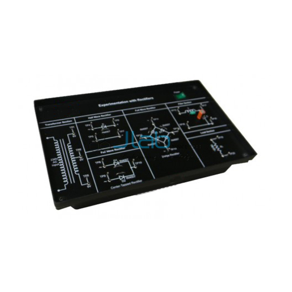

Digital Circuits Development Platform Manufacturer,Supplier and Exporter in India

Product Code : EL-BE-10486
Jlab Export is a leading Digital Circuits Development Platform Manufacturer,and suppliers in India
Digital Circuits Development Platform (code EL-BE-10486) is the 16-bit model of JLab's digital circuits trainer, a single board on which a digital electronics laboratory can run its experiments and students can try out circuits of their own. They explore a wide variety of electronic concepts by plugging components into the solderless breadboard, with no soldering. JLab makes this model in Ambala, India.
Specifications
| Parameter | Detail |
|---|---|
| Input switches | Pulser switches and 16-bit data switches |
| Output display | Bicolour 16-bit LED display |
| Circuit building | Solderless breadboard |
| Power supplies | On-board DC power supplies |
| Pulse generator | On-board, TTL/CMOS mode |
| Logic output | CMOS/TTL output |
| Display and test aids | BCD to seven-segment display; logic probe |
| Layout and operation | Functional blocks indicated on the board mimic; connections and controls clearly marked and conveniently located; self-contained and easy to operate |
| Learning support | Free e-learning course |
| Quality check | Each platform is visually inspected before dispatch |
| Pack quantity | Each (sold individually) |
| Minimum order quantity | 10 units |
| Dispatch time | Usually 7–10 working days |
| Product code | EL-BE-10486 |
| Manufacturer | Jain Laboratory Instruments Pvt Ltd (JLab) — OEM |
| Country of origin | India (made in Ambala, Haryana) |
How Does the 16-bit Model Compare with Other JLab Platforms?
| Model | Data switches and LED display | On-board supplies and signal source | Experiment focus |
|---|---|---|---|
| This platform (EL-BE-10486) | 16-bit data switches; bicolour 16-bit LED display | DC power supplies; pulse generator with TTL/CMOS mode | Encoder, multiplexer and de-multiplexer, equality detector, parity, SRAM and ALU circuits |
| Digital Circuits Development Platform (8-bit) | 8-bit data switches; bicolour 8-bit LED display | DC power supplies; pulse generator with TTL/CMOS mode | Adders, code conversion, up-down and Johnson counters, shift register, multiplexer and de-multiplexer, CMOS-TTL interfacing |
| Analog Digital Circuits Development Platform | 8-bit data switches; 8-bit LED display | DC and AC power supplies; sine/square/TTL generator | Analog and digital experiments on one board |
Pick this model when the course reaches memory, parity and arithmetic logic unit circuits. The 8-bit platform has the same on-board blocks with narrower switch and display banks and an experiment list centred on adders, code conversion and counters, and the Analog Digital platform is meant for labs that want one board for analog and digital practicals.
What Is the 16-bit Digital Circuits Development Platform Used For?
The platform is designed to cover the experiments of digital electronics in a single platform, and it is also useful for building and testing circuits and for digital electronics projects while learning the subject. Its experiment list takes in a 16 to 4 line encoder, an 8:1 multiplexer and a 1:16 de-multiplexer, an 8-bit equality detector, 12-bit odd and even parity generators with matching 13-bit parity checkers, writing data into and reading it from SRAM memory, and a 4-bit arithmetic logic unit.
What to Specify When Ordering
- Switch width — 16-bit (this model) or the 8-bit Digital Circuits Development Platform.
- Number of boards required.
- Companion trainers — any of the related items below, quoted on the same enquiry.
Frequently Asked Questions
Why is the parity generator 12-bit and the parity checker 13-bit?
The generator takes 12 data bits and adds one parity bit, chosen so that the total number of 1s is even (even parity) or odd (odd parity). The checker then examines all 13 bits, the data plus the parity bit, and signals an error if the parity no longer matches, which is how a single-bit transmission error is detected.
What does the 8-bit equality detector show?
It compares two 8-bit binary words bit by bit and gives an active output only when every pair of bits matches, the basic idea behind digital comparators and address decoding.
What is learnt from the SRAM experiment?
Students write data into static RAM at chosen addresses and read it back, which shows how address lines, data lines and read/write control work together in a memory chip.
What is the BCD to seven-segment display used for?
It shows a 4-bit binary-coded decimal value as a single decimal digit, so the output of an encoder or arithmetic circuit can be read at a glance instead of decoding the LEDs by hand.
What details help JLab prepare an export quotation?
Give the number of platforms, the country and the port or city of delivery, your preferred Incoterm such as FOB or CIF, any special packing or labelling, and the tender number where the purchase is through a tender.
Who makes this 16-bit platform?
JLab, the trading name of Jain Laboratory Instruments Pvt Ltd, makes it in Ambala, Haryana, and supplies it direct from its works.
OEM Manufacturer
Behind the JLab name is Jain Laboratory Instruments Pvt Ltd, a manufacturer of electronics lab equipment and other educational apparatus in India, incorporated in 2017 and based on Hargolal Road, Ambala, Haryana. Because the platform comes off JLab's own production line and not from a trading house, institutions, dealers and importers order straight from the factory, each board gets a visual inspection before dispatch, and the maker itself looks after follow-up orders. JLab exports worldwide and can deliver to every region, for example Uzbekistan in Central Asia, Mexico in North America, Singapore in Southeast Asia, Botswana in Southern Africa and Kenya in East Africa. Tender enquiries can start from the JLab lab tenders page.
Other Digital Electronics Trainers
- Digital Circuits Development Platform (8-bit data switches and LED display) — the 8-bit version compared above.
- Analog Digital Circuits Development Platform — combines analog and digital experiments, with a speaker and potentiometers on board.
- Understanding Digital Logic Circuits — on-board logic circuits shown with their schematic symbols, for verifying gate and RS, D and JK flip-flop truth tables.
- Digital Work Station — its graphical LCD lists the experiments and draws the gate-level diagram of the one selected.
- Experimentation with Logic Gates — a gate trainer powered by a +5V SMPS adaptor, with links made by patch cords, for AND, OR, NOT, NAND, NOR, XOR and XNOR truth tables.
See the full Basic Electronics range and all Electronics Lab Equipments.
Request a Quote
Send your requirement through the Add To Cart enquiry button above or the contact page; mention how many 16-bit platforms you need and where they should be delivered, and JLab will reply with a quotation.
Last updated: 22 October 2026