
Bernoullis Theorem Complete with Collecting Tank Manufacturer,Supplier and Exporter in India
Product Code : EL-TWL-9123
Jlab Export is a leading Bernoullis Theorem Complete with Collecting Tank Manufacturer,and suppliers in India
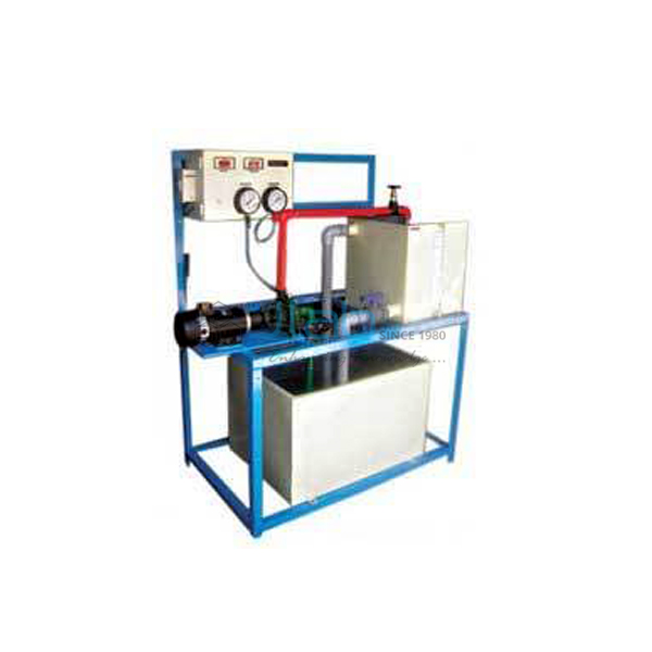
Water circulating in a closed loop runs through a one-piece clear acrylic duct that narrows and then widens again. Piezometer tubes at tappings along it show the pressure head falling at the throat and recovering downstream. Flow is timed into the collecting tank with the stopwatch supplied, so the velocity head at each tapping can be found and Bernoulli’s theorem checked.
Specifications
| Test section | One-piece clear acrylic, convergent and divergent parts |
| Pressure readings | Piezometer tubes at tappings along the section |
| Tanks | Supply tank, inlet water tank and measuring (collecting) tank, stainless steel |
| Wetted parts | Stainless steel |
| Water circulation | Pump, closed loop |
| Flow measurement | Measuring tank and stopwatch, supplied |
| Electric supply | 0.5 kW, 220 V AC, single phase |
| Water supply | Tap water connection 1/2 in BSP, distilled water 60 litres (optional) |
| Site | Floor area with drain |
| Minimum order quantity | 1 unit |
| Dispatch time | Usually 14–18 working days |
| Manufacturer | JLab (Jain Laboratory Instruments Pvt Ltd), Ambala, India |
Experiments for Fluid Mechanics Students
At each flow rate, students record every piezometer level, then time a known rise in the collecting tank to get the discharge Q. Velocity at a tapping is Q divided by the local area, and the velocity head is v²/2g. Drawn against distance along the duct, the pressure heads, the velocity heads and their totals give three lines on one graph. The total stays almost flat as far as the throat, then drops a little once the duct widens.
The same energy balance underlies flow meters. Classes often go on to calibrate the Venturi meter and Orifice Meter Apparatus, where the pressure difference across a throat gives the flow. The Pitot Static Tube Set-Up takes it further, reading point velocity from the difference between total and static head.
Frequently Asked Questions
Why does the total head fall slightly along the duct?
Bernoulli’s equation assumes no losses, but real water loses some energy to wall friction and, above all, to eddies in the divergent part where the flow slows down. The fall in total head between two tappings is the head lost between them.
How do I find the velocity at each tapping?
Time the rise in the collecting tank to get the discharge Q, then divide Q by the cross-section area of the duct at that tapping. The velocity is highest at the throat, where the area is smallest.
What services does the set-up need?
A single phase 220 V AC supply rated 0.5 kW, a tap water connection of 1/2 in BSP and a floor area with a drain. About 60 litres of distilled water can be used to fill the circuit if wanted.
Why fill the circuit with distilled water?
Distilled water leaves no scale and grows less algae, so the clear acrylic section and the piezometer tubes stay easy to read. It also keeps the meniscus clean, which makes level readings more consistent.
Other Bernoulli and Flow Measurement Rigs
- Bernoullis Theorem Apparatus
- Bernoulli Theorem Apparatus
- Bernoulli’s Principle
- Orifice and Mouthpiece Apparatus
For a quote, use Add To Cart or send us a message through the contact page.
Last updated: 6 November 2026