
Study of Transmitter and Receiver using Fiber Optics Cable Manufacturer,Supplier and Exporter in India
Product Code : EL-TKFCL-1198
Jlab Export is a leading Study of Transmitter and Receiver using Fiber Optics Cable Manufacturer,and suppliers in India
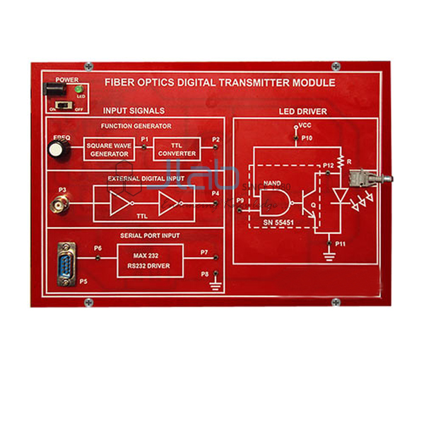
Study of Transmitter and Receiver using Fiber Optics Cable (code EL-TKFCL-1198) is a communication-lab trainer for building an optical transmitter and an optical receiver, sending a signal between them along a fiber optic cable and measuring how much of it is lost on the way. Its own 6 V and 3 V DC power supply is part of the instrument. It is made by Jain Laboratory Instruments Pvt Ltd (JLab) at its works in Ambala, India.
Specifications
| Parameter | Detail |
|---|---|
| Experiments | Construct an optical transmitter and calculate its output power; transmit a signal through the fiber optic cable; construct an optical receiver and calculate its output power; study the attenuation of the signal from the transmitter to the receiver end |
| Power supply | DC power supply, 6 V DC and 3 V DC, part of the instrument |
| Preamplifier stages | Microphone (MIC), photodetector, transistors and a biasing network of resistors and capacitors |
| Power amplifier stages | Impedance-matching (driver) transformers, transistors and a biasing network of resistors and capacitors |
| Output section | LEDs (light-emitting diodes) and speaker |
| Transmission medium | Fiber optic cable for transmission of the signal |
| Quality check | Each trainer is visually inspected before dispatch |
| Pack quantity | Each (sold individually) |
| Minimum order quantity | 10 units |
| Dispatch time | Usually 7–10 working days |
| Product code | EL-TKFCL-1198 |
| Manufacturer | Jain Laboratory Instruments Pvt Ltd (JLab) — OEM |
| Country of origin | India (made in Ambala, Haryana) |
What Is the Fiber Optic Transmitter and Receiver Trainer Used For?
It turns a basic optical communication link into a bench experiment for college physics and electronics laboratories, polytechnic and engineering communication labs and ITI electronics courses. Students set up the transmitter and work out its output power, pass the signal along the fiber optic cable, then set up the receiver and work out its output power. Comparing the two gives the attenuation of the link, which is normally expressed in decibels as 10 × log10 (input power ÷ output power).
The circuit follows the usual signal chain of a fiber optic link: preamplifier stages built around a microphone, a photodetector and transistors, power amplifier stages with impedance-matching driver transformers, and an output section with LEDs and a speaker. In any such link a light source converts the electrical signal into light, the fiber guides that light by total internal reflection, and a photodetector turns it back into an electrical signal. Handle the cable gently — avoid sharp bends and keep the fiber end faces clean, because tight bends and dirt both add loss.
What to Specify When Ordering
- Quantity — the minimum order is 10 trainers; plan one per bench group that will run the experiment.
- Fiber optic cable — the cable is part of the listing; state any length or connector you need so JLab can confirm it.
- Mains supply — give your mains voltage and plug type, as the input rating is not stated here.
- Measuring instruments — add an optical power meter, multimeter or oscilloscope to the same enquiry if your lab needs them for the readings.
Frequently Asked Questions
What experiments can students perform with this trainer?
Four are listed: constructing an optical transmitter and calculating its output power, transmitting a signal through the fiber optic cable, constructing an optical receiver and calculating its output power, and studying how the signal is attenuated between the transmitter and receiver ends.
Is the fiber optic cable included?
Yes. The instrument comprises a fiber optic cable for carrying the signal. Its length and connector type are not given in this listing, so mention any requirement in your enquiry.
What power supply does the trainer use?
A DC power supply giving 6 V and 3 V is part of the instrument and feeds its circuits. Confirm your mains voltage with JLab when ordering, since the mains input rating is not stated on this page.
How is the attenuation of the fiber link worked out?
By comparing the power at the transmitter end with the power that reaches the receiver end. The loss is usually given in decibels as 10 × log10 of the input power divided by the output power; a higher figure means more of the signal was lost along the cable.
How does it differ from the Elementary Fiber Optics Trainer?
This panel is built around discrete amplifier stages with a microphone, driver transformers, LEDs and a speaker. The Elementary Fiber Optics Trainer is listed as a simplex analog and digital transceiver with AM, FM and PWM modulation and demodulation; compare both listings, linked below, before choosing.
Who manufactures this trainer?
JLab — Jain Laboratory Instruments Pvt Ltd — makes it at its works in Ambala, Haryana, and quotes for it directly.
OEM Manufacturer
JLab is the trading name of Jain Laboratory Instruments Pvt Ltd, a manufacturer of electronics trainers and scientific laboratory equipment in India, incorporated in 2017 and based on Hargolal Road, Ambala, Haryana. This fiber optic trainer is made at JLab’s own works rather than bought from a trader, so colleges, institutes, dealers and importers buy it factory-direct; each unit is visually inspected before it leaves, and repeat orders and spare parts are handled by the manufacturer itself. JLab exports worldwide and ships to buyers in every region — for example the USA in North America, Morocco in North Africa, Estonia in Northern Europe, Tonga in Oceania and DR Congo in Central Africa. Institutions buying through a tender can find details on the JLab lab tenders page.
Related Fiber Optic and Communication Trainers
- Elementary Fiber Optics Trainer — a simplex analog and digital fiber optic transceiver with AM, FM and PWM modulation and demodulation.
- Advanced Fiber Optics Trainer — a full-duplex analog and digital trainer that includes experiments with an optical power meter.
- Fiber Optic Trainer — with on-board sine and square wave generators, a fiber optic LED transmitter and a photodetector receiver.
- Fiber Optic Power Meter — a germanium-photodiode meter for measuring optical power in fiber links.
- Study of Amplitude Modulation and Demodulation — a companion panel for AM experiments in the same communication lab range.
See every panel in the Training Kits for Communication Lab range or the wider Scientific Instrument range.
Request a Quote
Quotes come direct from the manufacturer. Use the Add To Cart enquiry button on this page, or send the quantity (minimum 10 units), any cable length or connector requirement, your mains voltage and the delivery location through the contact page.
Last updated: 9 October 2026