
Three Phase Fully Controlled Thyristorized Bridge Converter Manufacturer,Supplier and Exporter in India

Product Code : EL-PET-1443
Jlab Export is a leading Three Phase Fully Controlled Thyristorized Bridge Converter Manufacturer,and suppliers in India
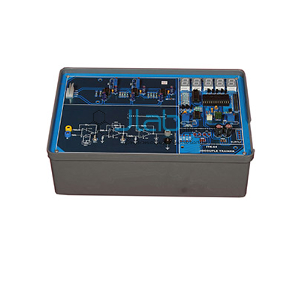
Three Phase Fully Controlled Thyristorized Bridge Converter (code EL-PET-1443) is a power electronics training board that combines a three-phase, line-commutated, fully controlled thyristor bridge with its complete triggering circuit. Students use it to study how the control signals are generated and how the bridge behaves with R and R-L loads, setting the firing angle with a single potentiometer. It is built in Ambala, India, by JLab (Jain Laboratory Instruments Pvt Ltd).
Specifications
| Parameter | Detail |
|---|---|
| Experiments | Nature and generation of the control signal for a three-phase full-wave controlled rectifier; operation of the bridge with R load; operation with R-L load; effect of the freewheeling diode on the output waveform |
| Power circuit | Three-phase line-commutated fully controlled thyristorized bridge converter |
| Triggering cards | Three identical cards, one per phase, each with zero crossing detector, integrator, comparator and pulse generator, controlling the firing angles of the positive group of three thyristors; a further card working with them for the negative group of three thyristors |
| Firing angle control | Potentiometer |
| Driver circuits | Six, with pulse transformers |
| Gate firing | High-frequency gated dual gate firing, 6 nos. |
| Triggering transformers | Three, 415 V : 6 V, AC supply for triggering |
| Rectification transformers | Three, 415 V : 50 V at 1 A |
| Triggering circuit supplies | ±12 V at 500 mA and 5 V at 500 mA, IC regulated |
| Load | R and L load with load voltage divider |
| Freewheeling diode | One |
| Meters | Two 3½-digit digital panel meters (DPM) for voltage and current |
| Switching and protection | Three-pole power contactor with AC coil and push-to-ON switch; four-pole miniature circuit breaker (MCB) |
| Oscilloscope sockets | Unearthed mains sockets for the CRO |
| Indicators | Three jewel lights, red, yellow and blue |
| Other components | Adequate number of other electronic components |
| Mains supply | Three-phase 415 V, 50 Hz AC |
| Patch cords | Adequate number, stackable, 4 mm spring-loaded plugs, ½ metre long |
| Terminals | Terminals and sockets at appropriate places on the panel for connections and observation of waveforms |
| Operating instructions | Detailed, with object, theory, design procedures, report suggestions and book references |
| Weight | 15 kg (approx.) |
| Dimensions | W 445 × H 260 × D 470 |
| Other apparatus required | Dual trace cathode ray oscilloscope, 20 MHz (unearthed) |
| Quality check | Each board is visually inspected before dispatch |
| Pack quantity | Each (sold individually) |
| Minimum order quantity | 10 units |
| Dispatch time | Usually 7–10 working days |
| Product code | EL-PET-1443 |
| Manufacturer | Jain Laboratory Instruments Pvt Ltd (JLab) — OEM |
| Country of origin | India (made in Ambala, Haryana) |
How Does It Compare with the Half Controlled Converter?
| Board | Bridge | Thyristor groups triggered | Driver circuits with pulse transformers | Dual gate firing | Weight (approx.) |
|---|---|---|---|---|---|
| This board (EL-PET-1443) | Fully controlled | Positive and negative groups, three thyristors each | Six | 6 nos. | 15 kg |
| Three Phase Half Controlled Thyristorized Bridge Converter | Half controlled | Positive group of three thyristors | Three | 3 nos. | 15 kg |
Both boards share the same enclosure size, three-phase 415 V supply, triggering-card design, R and L load, freewheel diode and pair of panel meters. Choose the fully controlled board when the syllabus covers firing both thyristor groups and the full-wave controlled bridge; the half-controlled board is the one for the half-controlled bridge.
What Is the Fully Controlled Bridge Converter Used For?
A three-phase fully controlled bridge turns three-phase AC into an adjustable DC output by delaying the firing of its six thyristors, one from the upper group and one from the lower group conducting at any time. With a resistive load the output voltage falls as the firing angle is increased; with an R-L load the inductance keeps the current flowing, so the output voltage can dip below zero for part of each cycle unless a freewheeling diode is connected. Converters of this type drive DC motors and supply controlled DC in industry. Science and engineering students use the board to follow the control signal from zero crossing detection to the gate pulses, and to see the load waveforms on an oscilloscope while reading voltage and current on the panel meters.
What to Specify When Ordering
- Quantity — the number of converter boards needed.
- Oscilloscope — whether one should be quoted with the boards.
- Related boards — for example the half-controlled converter or the three-phase full wave rectifier for the same course.
Frequently Asked Questions
Which transformers and supplies are built into the board?
Three 415 V : 50 V, 1 A transformers for rectification and three 415 V : 6 V transformers that give the AC supply for triggering, plus ±12 V and 5 V IC-regulated supplies for the triggering circuits. The board itself is fed from three-phase 415 V, 50 Hz mains through a four-pole MCB and a three-pole contactor.
Why does a fully controlled bridge need dual gate firing?
Load current always passes through one thyristor in the upper group and one in the lower group. When the converter starts, or when the current becomes discontinuous, both must be gated together, so each thyristor receives a second pulse when the next device in the sequence is fired. High-frequency gating sends each firing signal as a burst of short pulses, which a small pulse transformer can pass without saturating.
What does the freewheeling diode change?
With an R-L load, the diode clamps the output at about zero instead of letting it swing negative, and carries the load current during that part of the cycle. The average DC output rises, and the difference shows clearly when the waveforms with and without the diode are compared.
What other apparatus is needed?
A 20 MHz dual trace cathode ray oscilloscope, used unearthed; the board provides unearthed mains sockets for it. JLab’s Dual Trace Oscilloscope is a separate item that can be quoted on the same enquiry.
How does it differ from the half-controlled converter?
This board fires both thyristor groups, with six driver circuits, while the half-controlled board triggers only the positive group of three thyristors. The table above shows the details.
What should an export enquiry state?
The number of boards, the destination country and port or city, the delivery terms (for example FOB or CIF), any packing or labelling requirements and the tender reference where one applies.
Who manufactures this three-phase converter?
Jain Laboratory Instruments Pvt Ltd, trading as JLab, makes it at its works in Ambala, Haryana, India.
OEM Manufacturer
JLab is the trading name of Jain Laboratory Instruments Pvt Ltd, a manufacturer of power electronics trainers and engineering lab equipment in India, incorporated in 2017 and located on Hargolal Road, Ambala, Haryana. This converter is assembled at JLab’s own works and not bought in from a trader, so colleges, institutes, dealers and importers order directly from the manufacturer; each board is visually inspected before dispatch, and repeat orders are made by the same works. JLab exports worldwide and ships to buyers in every region — for example Namibia in Southern Africa, Canada in North America, Lithuania in Northern Europe, El Salvador in Central America and the Caribbean and Colombia in South America. Tender buyers can refer to the JLab lab tenders page.
Related Three-Phase Power Electronics Trainers
- Three Phase Half Controlled Thyristorized Bridge Converter — the half-controlled bridge, with triggering cards for the positive thyristor group.
- Three Phase Full Wave Rectifier — an uncontrolled six-diode bridge with a resistive load and two digital panel meters.
- Single Phase Fully Controlled Bridge Converter — a single-phase converter board with four SCRs, two UJTs and two 1:1:1 pulse transformers.
- Dual Trace Oscilloscope — a 20 MHz dual-channel cathode ray oscilloscope, sold separately.
The complete range is in Power Electronics Trainers, part of Electronics Lab Equipments.
Request a Quote
Use the Add To Cart button on this page or the contact page to ask for a quotation, giving the number of boards, the delivery destination and any related trainers or instruments to add.
Last updated: 22 October 2026