
Firing Circuit Using Ramp Comparator Scheme Manufacturer,Supplier and Exporter in India

Product Code : EL-PET-1434
Jlab Export is a leading Firing Circuit Using Ramp Comparator Scheme Manufacturer,and suppliers in India
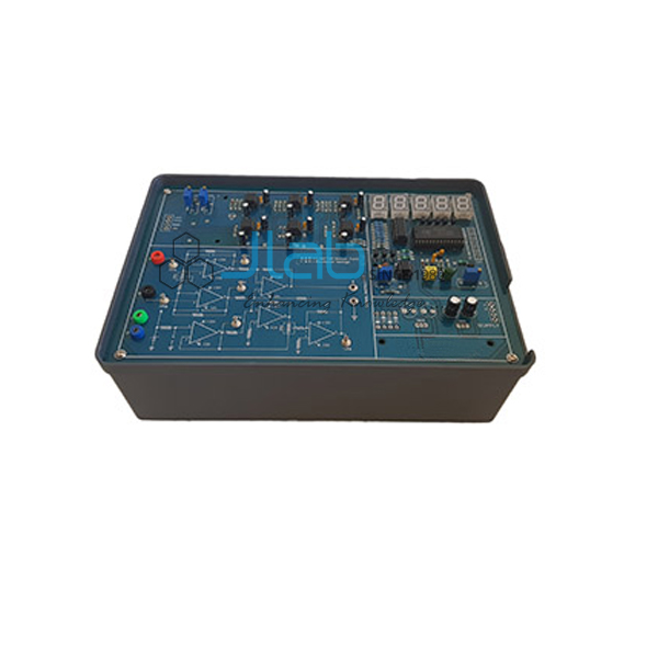
Firing Circuit Using Ramp Comparator Scheme (code EL-PET-1434) is a power electronics training board on the ramp-comparator method of firing a single-phase converter. Its firing circuit uses two op-amp ICs and four logic-gate ICs, with a potentiometer for reference voltage adjustment and a 1:1 pulse transformer on the panel. The trainer is made by JLab, the Ambala, India, manufacturer Jain Laboratory Instruments Pvt Ltd.
Specifications
| Parameter | Detail |
|---|---|
| Experiment | Study of the firing circuit for a single-phase converter using the ramp comparator scheme |
| AC supply | 6 V AC at 100 mA |
| DC supply | ±12 V DC at 100 mA, fixed regulated |
| Op-amps | Two op-amp ICs |
| Logic ICs | Quad Ex-OR gate IC; triple 3-input AND gate IC; hex inverter gate IC; quad two-input AND gate IC |
| Transistors | Two NPN |
| Reference adjustment | Potentiometer for reference voltage adjustment |
| Pulse transformer | 1:1 |
| Other components | Adequate number of other electronic components |
| Mains controls | Mains ON/OFF switch, fuse and jewel light |
| Mains supply | 230 V ±10%, 50 Hz AC |
| Patch cords | Adequate number, stackable, 4 mm spring-loaded plugs, ½ metre long |
| Terminals | Terminals and sockets on the panel for connections and observation of waveforms |
| Operating instructions | Detailed: object, theory, design procedures, report suggestions and book references |
| Weight | 3 kg (approx.) |
| Dimensions | W 340 × H 110 × D 210 |
| Other apparatus required | Dual-trace cathode ray oscilloscope, 20 MHz (unearthed) |
| Optional load unit | Separate unit for the experiment to work into a load, with a 50 W isolation transformer, a 40 W lamp, a 400 V, 4 A SCR, and a mains ON/OFF switch, fuse and jewel light |
| Quality check | Each board is visually inspected before dispatch |
| Pack quantity | Each (sold individually) |
| Minimum order quantity | 10 units |
| Dispatch time | Usually 7–10 working days |
| Product code | EL-PET-1434 |
| Manufacturer | Jain Laboratory Instruments Pvt Ltd (JLab) — OEM |
| Country of origin | India (made in Ambala, Haryana) |
What Is the Ramp Comparator Firing Circuit Used For?
Every phase-controlled converter needs a firing circuit that places a gate pulse at the same, adjustable point in each half-cycle and keeps it locked to the supply. The ramp-comparator scheme is one of the standard ways of doing this with analogue and digital ICs, and it is widely used in thyristor converters and drives. Working on the firing circuit by itself lets students study the control side in detail and observe its waveforms on an oscilloscope at the panel terminals, before or alongside complete converter trainers.
What to Specify When Ordering
- The number of firing-circuit boards.
- Whether the optional load unit and an oscilloscope should be quoted as well.
- Companion converter boards, such as the half-controlled or fully controlled bridge trainers, if you are building a converter laboratory.
- The delivery destination, delivery terms and any tender reference.
Frequently Asked Questions
How does a ramp-comparator scheme set the firing angle?
A ramp synchronised to the AC supply is compared with a DC control (reference) voltage. The comparator switches at the instant the ramp crosses the control voltage, and that instant becomes the firing point, so the firing angle varies linearly with the control voltage; logic gates then shape the result into gate pulses.
Is there a load unit for the experiment?
Yes, as an option. The optional unit lets the experiment work into a load and has a 50 W isolation transformer, a 40 W lamp, a 400 V, 4 A SCR and its own mains ON/OFF switch, fuse and jewel light. It can be quoted on the same enquiry.
Which supplies are on the board?
A 6 V AC, 100 mA supply and a ±12 V DC, 100 mA fixed regulated supply. The board is powered from 230 V ±10%, 50 Hz AC mains.
What other apparatus is required?
A 20 MHz dual-trace cathode ray oscilloscope of the unearthed type. JLab’s 20 MHz dual-trace oscilloscope is linked below as a separate item.
How does it differ from the Firing Circuit Using OP AMPS And Gates board?
That board has eight op-amps, a quad two-input AND gate IC, two NPN transistors, two 1:1 pulse transformers and three potentiometers. This board is built around the ramp comparator scheme and has a single 1:1 pulse transformer.
What should an export enquiry include?
The quantity, the destination country and port or city, the delivery terms you want (for example FOB or CIF), packing or labelling requirements, and the tender reference for a tender order.
Who manufactures this firing circuit board?
JLab (Jain Laboratory Instruments Pvt Ltd) manufactures it at its works in Ambala, Haryana, India.
OEM Manufacturer
JLab is the trading name of Jain Laboratory Instruments Pvt Ltd, a manufacturer of power electronics trainers and laboratory equipment in India, incorporated in 2017 and based on Hargolal Road, Ambala, Haryana. The firing circuit board, and its optional load unit, are built at JLab’s own works rather than bought from a trader, so colleges, polytechnics, dealers and importers deal with the manufacturer directly; each board is visually inspected before dispatch, and repeat orders are supplied by the same works. JLab exports worldwide and ships to buyers in every region — for example New Zealand in Oceania, Burkina Faso in West Africa, Tunisia in North Africa, Bahrain in the Middle East and Botswana in Southern Africa. Tender buyers can see the JLab lab tenders page.
Related Firing-Circuit and Converter Boards
- Firing Circuit Using OP AMPS And Gates — gate-pulse generation for a single-phase converter with op-amps and logic gates.
- Single Phase Half Controlled Symmetrical — symmetrical and asymmetrical half-controlled bridges with an op-amp and logic-gate firing circuit.
- Single Phase Fully Controlled Bridge Converter — a four-SCR single-phase bridge with UJT firing.
- SCR Triggering Circuit — controlled gate pulses from a signal conditioner and pulse generator IC.
- Triggering Circuits for SCR — R, R-C and UJT triggering circuits and controlled rectifiers.
- Dual Trace Oscilloscope — a 20 MHz dual-channel oscilloscope.
Browse all Power Electronics Trainers or the full Electronics Lab Equipments range.
Request a Quote
Ask for a quotation using the Add To Cart enquiry button on this page or the contact page, and mention the number of boards, the delivery destination and whether the optional load unit is needed.
Last updated: 22 October 2026