
Half Wave, Full Wave and Rectifier Apparatus Manufacturer,Supplier and Exporter in India
Product Code : EL-VOVLACOS-1113
Jlab Export is a leading Half Wave, Full Wave and Rectifier Apparatus Manufacturer,and suppliers in India
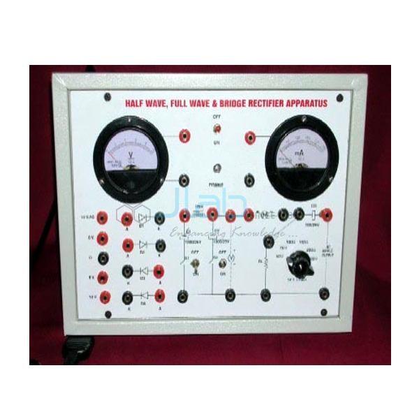
Half Wave, Full Wave and Rectifier Apparatus (code EL-VOVLACOS-1113) is a rectifier circuit kit for the lab bench, used to measure the efficiency and ripple factor of half-wave, full-wave and bridge rectifiers on load and to study filters. Load resistances are switched in with toggle switches, and two meters read the output voltage and current. It is made by Jain Laboratory Instruments Pvt Ltd (JLab) at its works in Ambala, India.
Specifications
| Parameter | Detail |
|---|---|
| Experiments | Efficiency and ripple factor of half-wave, full-wave and bridge rectifiers on load; study of filters |
| Power supply | AC power supply built in |
| Meters | Two, for output voltage and output current |
| Rectifying elements | Junction diodes |
| Filters | Filter circuit kit |
| Load | Load resistances selected with toggle switches |
| Connections | All important connections on terminals |
| Dimensions | 10 x 8 x 4 in (about 25 x 20 x 10 cm) |
| Optional accessory | Digital AC millivoltmeter |
| Quality check | Each apparatus is visually inspected before dispatch |
| Pack quantity | Each (sold individually) |
| Minimum order quantity | 10 units |
| Dispatch time | Usually 7–10 working days |
| Product code | EL-VOVLACOS-1113 |
| Manufacturer | Jain Laboratory Instruments Pvt Ltd (JLab) — OEM |
| Country of origin | India (made in Ambala, Haryana) |
How Does It Compare with Other JLab Rectifier Apparatus?
| Model | Rectifier circuits | Filters | Meters and supply (as listed) |
|---|---|---|---|
| This apparatus (EL-VOVLACOS-1113) | Half wave, full wave and bridge; efficiency and ripple factor on load | Filter circuit kit (types not listed) | Two meters for output voltage and current; AC supply; toggle-switched loads; optional digital AC millivoltmeter |
| Half Wave, Full Wave and Bridge Rectifier Apparatus | Half wave, full wave and bridge, each at different loads | Two filters | Inbuilt variable AC supply; analog moving-coil voltmeter and ammeter; four diodes |
| Junction Diode Rectifier and Filter | Half wave, centre-tap full wave, bridge and a voltage doubler | Capacitor, inductor, capacitor-input L-section and pi-section filters | Built-in mains transformer; digital DC voltmeter and current meter |
Choose this apparatus when the practical is built around efficiency and ripple factor with switched loads and you want a compact unit with terminal connections. The bridge rectifier apparatus suits labs that prefer an inbuilt variable supply and analog meters, and the junction diode training board covers more filter types and a voltage doubler.
What Is the Half Wave and Full Wave Rectifier Apparatus Used For?
A rectifier turns alternating current into direct current. A half-wave rectifier passes only one half of each cycle, a centre-tap full-wave rectifier uses two diodes to pass both halves, and a bridge rectifier does the same with four diodes and no centre-tapped winding. Students measure the DC output voltage and current for each circuit at several load settings and work out the efficiency, the ratio of DC output power to AC input power, and the ripple factor, the ratio of the AC ripple left on the output to the DC value; the optional digital AC millivoltmeter is useful for reading that small ripple voltage. Full-wave and bridge circuits give a higher efficiency and far less ripple than the half-wave circuit, which the readings show directly.
Adding the filters shows how the output is smoothed: a capacitor across the load charges to near the peak and discharges between peaks, so the ripple falls, and it rises again as the load draws more current. The apparatus supports the rectifier topic of class 12 physics, B.Sc. physics and electronics practicals, and diploma, engineering and ITI electronics labs. Switch off before changing connections and let filter capacitors discharge before touching the terminals.
What to Specify When Ordering
- Digital AC millivoltmeter — say whether you want this optional meter for ripple measurement.
- Meter ranges and filter types — the listing does not give them; ask JLab if your worksheet depends on particular values.
- Quantity — the minimum order is 10 units.
Frequently Asked Questions
Which rectifier circuits does this apparatus cover?
Half-wave, full-wave and bridge rectifiers, each studied on load for efficiency and ripple factor, plus the effect of the filter circuits.
Does the name leave out the bridge rectifier?
The product name reads "Half Wave, Full Wave and Rectifier", but the listed experiments include the bridge rectifier, so all three circuits are part of the study.
How is the ripple factor measured?
Read the DC output on the voltage meter and the AC ripple on an AC millivoltmeter, then divide the ripple by the DC value. A digital AC millivoltmeter is offered as an option for this.
Can the load be changed?
Yes. Load resistances are selected with toggle switches, so efficiency and ripple can be compared at different loads.
Who manufactures this apparatus?
Jain Laboratory Instruments Pvt Ltd, trading as JLab, at its works in Ambala, Haryana, India.
OEM Manufacturer
JLab is the trading name of Jain Laboratory Instruments Pvt Ltd, an Indian manufacturer of physics and electronics teaching apparatus, incorporated in 2017 with its works on Hargolal Road, Ambala, Haryana. This rectifier apparatus is produced in-house rather than bought from a trader, so schools, colleges, dealers and importers deal with the maker directly; each unit is visually inspected before dispatch, and repeat orders and replacement parts are handled at the works. JLab exports worldwide and ships to buyers in every region — for example New Zealand in Oceania, Brazil in South America, Ukraine in Eastern Europe, Guinea in West Africa and Canada in North America. Tender details are on the JLab lab tenders page.
Related Diode Circuit Apparatus
- Half Wave, Full Wave and Bridge Rectifier Apparatus — an alternative rectifier unit with an inbuilt variable AC supply and analog meters.
- Junction Diode Rectifier and Filter — a training board with more filter types and a voltage doubler.
- Semiconductor Diode and PN Junction Diode Apparatus — forward and reverse characteristics of the junction diode.
- Voltage Stabilization Characteristics of Zener Diode — the regulation stage that usually follows rectification and filtering.
- Clipping and Clamping Circuit Apparatus — diode wave-shaping circuits on a sine wave.
See the full Verification of Various Laws and Conservation of Signal range or all Scientific Instrument apparatus.
Request a Quote
Quotes come direct from the manufacturer. Use the Add To Cart enquiry button, or send the quantity (minimum 10 units), whether you need the digital AC millivoltmeter, and your delivery location through the contact page.
Last updated: 9 October 2026