
Analog Electronics Trainer Manufacturer, Suppliers and Exporter in India
Jlabexport is a leading Analog Electronics Trainer Manufacturer,and suppliers in India, United States, Indonesia, Brazil, Bangladesh, Mexico, Japan, Egypt, Philippines, Democratic Republic of the Congo, Vietnam, Iran, Turkey, Tanzania, United Kingdom, France, South Africa, Italy, Kenya, Colombia, Sudan, Uganda, South Korea, Argentina, Afghanistan, Yemen, Angola, Morocco, Poland, Uzbekistan, Mozambique, Malaysia, Ghana, Saudi Arabia, Peru, Madagascar, Côte d’Ivoire, Cameroon, Niger, Venezuela, Australia, Syria, Mali, Burkina Faso, Sri Lanka, Malawi, Zambia, Chad, Kazakhstan, Somalia, Chile, Senegal, Ecuador, Cambodia, Zimbabwe, Guinea, Benin, Rwanda, Burundi, Bolivia, South Sudan, Tunisia, Haiti, Belgium, Dominican Republic, Jordan, United Arab Emirates, Honduras, Tajikistan, Papua New Guinea, Portugal, Togo, Sierra Leone, Belarus, Laos, Turkmenistan, Libya, Kyrgyzstan, Nicaragua, Paraguay, Bulgaria, Serbia, Republic of the Congo, Lebanon, Liberia, Central African Republic, Palestine, Oman, Mauritania, New Zealand, Costa Rica, Kuwait, Panama, Croatia, Georgia, Eritrea, Mongolia, Uruguay, Qatar, Namibia, Bosnia and Herzegovina, Moldova, Armenia, Gambia, Jamaica, Lithuania, Albania, Gabon, Botswana, Lesotho, Guinea-Bissau, Slovenia, Equatorial Guinea, Latvia, North Macedonia, Bahrain, Trinidad and Tobago, Timor-Leste, Cyprus, Estonia, Eswatini, Mauritius, Djibouti, Fiji, Comoros, Solomon Islands, Guyana, Bhutan, Luxembourg, Suriname, Montenegro, Malta, Maldives, Cabo Verde, Brunei, Belize, Bahamas, Iceland, Vanuatu, Barbados, São Tomé and Príncipe, Samoa, Saint Lucia, Kiribati, Seychelles, Grenada, Saint Vincent and the Grenadines, Antigua and Barbuda.
Last updated: 14 November 2026
What Are Analog Electronics Trainers?
Analog electronics trainers are bench boards on which students build and measure the circuits of a basic electronics course. Each board carries its devices, its own mains-powered DC supply and, on most device boards, the meters, with terminals for 4 mm patch cords. The range covers diode, transistor, MOSFET and thyristor characteristics, amplifiers and an RF oscillator, AC bridges, networks and filters, DC circuit practicals and two fiber optic links. JLab (Jain Laboratory Instruments Pvt Ltd), Ambala, India, makes all 31 trainers listed here.
Request a quotation | Compare the trainers | See the practicals covered
Which Trainers Are in the Analog Electronics Range?
| Group | Items | What it covers |
|---|---|---|
| Diode, Rectifier and Opto Boards | 5 | Germanium, silicon and zener diode curves, the energy band gap, rectifiers with five filter types, and LED, LDR, photodiode, phototransistor, solar cell and opto coupler studies. |
| Transistor, MOSFET and Thyristor Boards | 6 | Transistor curves in three configurations, MOSFET drain curves, and UJT, SCR, triac and DIAC characteristics with their switching applications. |
| Amplifier and Oscillator Boards | 6 | Emitter follower, two-stage RC coupled, multistage, class B push-pull and differential amplifiers, and a tunable RF oscillator. |
| AC Bridge Boards | 5 | Anderson, De Sauty, Wien and Schering bridges and a board for unknown inductance and capacitance. |
| Network, Filter and DC Circuit Boards | 7 | T and π networks, series and parallel resonance, passive and active filters, condenser charging, Ohm's law and galvanometer conversion. |
| Fiber Optic Trainers | 2 | Simplex and full-duplex fiber links with AM, FM and PWM, a voice link and, on one model, PC-to-PC data. |
Compare Analog Electronics Trainers by Specification
Each table sets the trainers of one group side by side, using the experiment, supply and meter rows of each product page. All boards run from 230 V, 50 Hz mains.
Diode, Rectifier and Opto Boards (5)
| Trainer | Experiment | Built-in supply | Meters |
|---|---|---|---|
| Training Board for Diode and Zener Diode | Forward and reverse curves of a germanium diode and a zener diode | 0–10 V DC, 10 mA | Digital voltmeter 2/20 V; digital current meter |
| Semiconductor Diode | Ge and Si diode curves; static and dynamic resistance | 0–10 V DC, 50 mA, coarse and fine | Digital voltmeter 2/20 V; digital current meter |
| Determination of Energy Band Gap in Semiconductor Diode | Reverse saturation current against temperature; band gap | 2 V DC, 10 mA, with diode oven | Digital microammeter; 0–110 °C thermometer |
| Junction Diode Rectifier and Filter | Half-wave, centre-tap, bridge and doubler output, ripple and load regulation | 100-0-100 V, 100 mA transformer | Digital voltmeter 1000 V; current meter 200 mA |
| Opto Electronic Devices | LED, photodiode, phototransistor, LDR, photovoltaic cell and opto coupler | Two 0–10 V DC, 100 mA | Digital voltmeter; two digital current meters |
Transistor, MOSFET and Thyristor Boards (6)
| Trainer | Experiment | Built-in supplies | Meters |
|---|---|---|---|
| Training Board for Transistor | Input and output curves in CE, CB and CC; Si and Ge, NPN and PNP | Two 0–10 V DC, 50 mA | Two digital voltmeters; two current meters |
| Training Board for MOSFET | Drain curves; common source amplifier gain | 0–15 V, 0–4 V and 0–1 V DC | Not listed |
| Unijunction Transistor | UJT V-I curve; relaxation oscillator | Two 0–30 V DC, 50 mA | 0–30 V voltmeter; 0–5 mA ammeter |
| Silicon Controlled Rectifier | Gate firing, anode current, holding current, phase firing | 0–50 V and 0–3 V DC; 0–10 V AC | Digital voltmeter 20/200 V; current meter 200 mA |
| Training Board for Triac | Gate modes I+, I−, III+, III−; static switch; holding current | 0–70 V and 0–3 V DC; 55 V and 7 V AC | Not listed |
| Training Board for DIAC | Break-over voltage, negative resistance; sawtooth and pulse generator | 0–50 V DC; 45 V AC | 0–50 V voltmeter; two-range ammeter |
Amplifier and Oscillator Boards (6)
| Trainer | Circuit studied | Built-in supply | Devices or signal source |
|---|---|---|---|
| Emitter Follower CC | Voltage gain, input and output impedance of an emitter follower | +9 V DC, 50 mA | One NPN transistor |
| Two Stage RC Coupled Transistor Amplifier | Overload, frequency response and impedances of each stage and the cascade | −12 V DC | Two PNP transistors |
| BJT Amplifiers and Emitter Follower Trainer | Multistage amplifier and emitter follower | +12 V and +5 V DC | Sine generator, 10 Hz to 100 kHz, 0–5 Vpp |
| Push Pull Amplifier | Class B output power, frequency response and distortion, four loads | −9 V DC, 50 mA | Three PNP transistors; driver and output transformers |
| Power and Differential Amplifier Trainer | Differential amplifier and class B push-pull amplifier | ±12 V and ±5 V fixed; 0–1 V variable | Sine generator, 800 Hz to 8 kHz, 0–5 Vpp |
| RF Oscillators | Tuning an RF transistor oscillator with a variable gang condenser | −9 V DC, 50 mA | One PNP transistor |
AC Bridge Boards (5)
| Trainer | Measurement | Signal source | Null detector |
|---|---|---|---|
| Anderson Bridge | Inductance of a coil; three inductances, five capacitors | 1 kHz sine oscillator | Audio amplifier and speaker |
| Measurement of Inductance and Capacitance | Five unknown capacitors and three unknown inductors | 1 kHz sine oscillator | Audio amplifier and speaker |
| De Sauty Bridge | Comparison of two capacitances with decade arms | External bridge oscillator | High-impedance headphone |
| Wien Bridge | Capacitance by the Wien series and parallel bridge | 1 kHz sine oscillator | Audio amplifier and speaker |
| Schering Bridge Trainer | Three unknown capacitors; six resistance values | 1 kHz sine oscillator, 0–15 Vpp | Audio amplifier and speaker |
Network, Filter and DC Circuit Boards (7)
| Trainer | Experiment | Built in | Also needed |
|---|---|---|---|
| T and P Network Trainer | Image impedance of unsymmetrical T and π networks; characteristic impedance of symmetrical ones | 5 V DC, 150 mA | Not listed |
| Series and Parallel Resonance | Resonance curves, Q, dielectric constant of a liquid | Three each of L, C and R, switch selected | AF generator; AC and AF millivoltmeters |
| Passive Filters | Constants and cut-off of constant-K and m-derived filters | Constant-K LP, HP, BP; m-derived LP, HP | AF generator; AC millivoltmeter |
| Active Filters | Low-pass, high-pass, band-pass and notch filter curves | Four op-amp ICs; ±12 V DC | Decade AF generator; AC millivoltmeter |
| Charging and Discharging of a Condenser | Voltage and current against time; time constant | 0–20 V DC; four electrolytic condensers | Digital stop clock; DC voltmeter; DC current meter |
| Ohm's Law Series and Parallel Circuits | Ohm's law; series and parallel circuits | 0–15 V DC; 20 V voltmeter; 200 mA meter | Not listed |
| Conversion of Galvanometer into an Ammeter | Resistance by half deflection; figure of merit; conversion and calibration | +5 V DC; 30-0-30 galvanometer; 0–50 mA meter | Not listed |
Fiber Optic Trainers (2)
| Trainer | Link | Wavelengths | Other features |
|---|---|---|---|
| Elementary Fiber Optics Trainer | Simplex analog and digital; AM, FM, PWM | 660 nm | Voice link; function generator; switched faults; 0.5 m and 1 m PMMA fiber |
| Advanced Fiber Optics Trainer | Full duplex analog and digital; AM, FM, PWM | 660 nm and 950 nm | PC-to-PC RS232 link; voice link; NA jig and mandrel |
How to Choose Analog Electronics Trainers for Your Lab
- Start from the syllabus list. Match each practical to a board in the practicals table, then count the student groups in one batch. Each board covers one topic, so a full course needs a set of boards.
- Check the instruments you already have. The diode, transistor, opto and SCR boards carry their own meters. The amplifier, filter and resonance boards need an audio frequency generator and an AC millivoltmeter, and the SCR, triac, DIAC, UJT and MOSFET pages list a 20 MHz oscilloscope.
- Single-topic boards or combined trainers. The Emitter Follower CC and Push Pull Amplifier boards each study one circuit with outside instruments. The BJT Amplifiers and Emitter Follower Trainer and the Power and Differential Amplifier Trainer carry their own sine-wave generator and cover two circuits each.
- Germanium, silicon or both. The Semiconductor Diode board has a Ge and a Si diode for comparison. The Diode and Zener Diode board pairs a germanium diode with a zener, and the transistor board carries Si and Ge transistors of both polarities.
- Bridge by method. Choose the Anderson bridge for inductance, the De Sauty, Wien or Schering bridge for capacitance, and the Measurement of Inductance and Capacitance board when one panel should cover both. The De Sauty board needs an outside bridge oscillator.
- Simplex or duplex fiber link. The Elementary Fiber Optics Trainer runs one 660 nm channel. The Advanced model adds a 950 nm channel for full duplex work and a PC-to-PC data link.
Practicals Covered by the Analog Electronics Trainer Range
| Practical | Trainer |
|---|---|
| Forward and reverse characteristics of germanium and silicon diodes; static and dynamic resistance | Semiconductor Diode; Training Board for Diode and Zener Diode |
| Zener diode forward and reverse (breakdown) characteristics | Training Board for Diode and Zener Diode |
| Energy band gap of a P-N junction diode | Determination of Energy Band Gap in Semiconductor Diode |
| Half-wave, full-wave and bridge rectifiers and voltage doubler: ripple and load regulation with filters | Junction Diode Rectifier and Filter |
| Characteristics of LED, photodiode, phototransistor, LDR, photovoltaic cell and opto coupler | Opto Electronic Devices |
| Transistor input and output characteristics in CE, CB and CC | Training Board for Transistor |
| MOSFET drain characteristics and common source amplifier gain | Training Board for MOSFET |
| UJT V-I characteristics and relaxation oscillator | Unijunction Transistor |
| SCR gate firing, anode characteristics, holding current and phase firing | Silicon Controlled Rectifier |
| Triac gate characteristics, static switch and holding current | Training Board for Triac |
| DIAC V-I characteristics and sawtooth generator | Training Board for DIAC |
| Emitter follower: voltage gain, input and output impedance | Emitter Follower CC; BJT Amplifiers and Emitter Follower Trainer |
| Frequency response of an RC coupled or multistage amplifier | Two Stage RC Coupled Transistor Amplifier; BJT Amplifiers and Emitter Follower Trainer |
| Class B push-pull amplifier: output power and distortion | Push Pull Amplifier; Power and Differential Amplifier Trainer |
| Working of a differential amplifier | Power and Differential Amplifier Trainer |
| Tuning an RF oscillator | RF Oscillators |
| Inductance by the Anderson bridge | Anderson Bridge |
| Capacitance by the De Sauty, Wien and Schering bridges | De Sauty Bridge; Wien Bridge; Schering Bridge Trainer |
| Unknown inductance and capacitance | Measurement of Inductance and Capacitance |
| Image and characteristic impedance of T and π networks | T and P Network Trainer |
| Series and parallel resonance and Q factor | Series and Parallel Resonance |
| Cut-off frequency of passive and active filters | Passive Filters; Active Filters |
| Charging and discharging of a condenser: time constant | Charging and Discharging of a Condenser |
| Verification of Ohm's law; series and parallel circuits | Ohm's Law Series and Parallel Circuits |
| Galvanometer resistance, figure of merit and conversion into an ammeter | Conversion of Galvanometer into an Ammeter |
| Analog and digital transmission over optical fiber with AM, FM and PWM | Elementary Fiber Optics Trainer; Advanced Fiber Optics Trainer |
Who Uses Analog Electronics Trainers?
Electronics and physics laboratories of polytechnics, engineering colleges and degree colleges use these boards for device, amplifier, bridge and network practicals. Senior secondary physics labs use the diode, Ohm's law, condenser and galvanometer boards.
Ordering, Minimum Quantity and Dispatch
| Point | Detail |
|---|---|
| Minimum order quantity | 10 units of each trainer, as shown on its product page |
| Pack quantity | Each trainer is sold individually |
| Dispatch time | Usually 7–10 working days |
| How to enquire | Use Add To Cart on a product page, or send the trainer names and quantities through the contact page |
| Tenders and OEM supply | Send the schedule through the tender enquiry page |
| Manufacturer | JLab (Jain Laboratory Instruments Pvt Ltd), Ambala, India |
Related Ranges in Electronics Lab Equipment
Analog Electronics Trainer is one of the ranges of Electronics Lab Equipments. These neighbouring ranges add instruments and later topics.
| Range | How it relates |
|---|---|
| Signal Generators | Function generators from 2 MHz to 15 MHz and a 150 MHz RF signal generator, the outside signal source many amplifier and filter boards need. |
| Oscilloscopes | An oscilloscope, an oscilloscope with digital readout and a frequency counter for viewing waveforms on the boards. |
| Power Electronics Trainers | SCR and triac phase control, triggering circuits, converters, inverters and motor speed control, the next step after thyristor characteristics. |
| Digital Electronics Trainer | Logic gate, flip-flop, counter, multiplexer, decoder and ADC and DAC training boards. |
| Breadboard Trainers | Digital and logic trainers with solderless breadboards, an analog lab station with supplies and a function generator, and electricity trainers. |
| Communication Trainer | Amplitude, frequency, pulse and digital modulation trainers, transmission line, AM transmitter and receiver and LAN trainers. |
| Fiber Optic Trainers | Fibre optic transceiver, numerical aperture, voice link and laser diode modulation trainers and a fiber optic power meter. |
| Basic Electronics | Analog and digital circuit development platforms and experiment boards for diodes, transistors, rectifiers, op-amps and oscillators. |
Frequently Asked Questions
Which outside instruments do the boards need?
It depends on the board. The diode, transistor, opto, SCR and DC circuit boards have their supplies and meters built in. The amplifier, filter and resonance boards need an audio frequency generator and an AC millivoltmeter. The SCR, triac, DIAC, UJT and MOSFET pages also list a 20 MHz oscilloscope for waveforms.
What is the difference between static and dynamic resistance of a diode?
Static resistance is the voltage divided by the current at one point of the forward curve. Dynamic resistance is the small change in voltage divided by the small change in current, the slope of the curve at that point. It falls sharply once the diode conducts.
How does a filter change the ripple factor of a rectifier?
Ripple factor is the rms value of the AC part of the output divided by the DC output. Without a filter it is about 1.21 for a half-wave and about 0.48 for a full-wave rectifier. A capacitor or L section filter lowers it, and the ripple rises again as the load current increases.
Why does a class B push-pull stage show crossover distortion?
Each transistor stays off until its base-emitter voltage reaches about 0.6 V for silicon. Near the zero crossing of the signal neither transistor conducts, so the output waveform shows a small flat step. Students see it on an oscilloscope at low input levels.
How do students know an AC bridge is balanced?
By listening to the null detector. The 1 kHz tone from the speaker or headphone falls to a minimum at balance. Students adjust the resistance and capacitance arms in turn, each time for the lowest sound, and then read the arm values into the balance equation.
Request a Quote
List each trainer by its name with the number of boards, for example ten Training Board for Transistor and five Anderson Bridge, and say whether the boards are for one batch or several. Then send the list from the contact page.


RF Oscillators
Product Code : EL-AET-1452
-9V DC at 50 mA, IC regulated power supply internally connected PNP transistor Variable gang condenser Adequate no. of other electronic components Mains on/off switch, fuse and jewel light.
View Details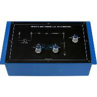
Series and Parallel Resonance
Product Code : EL-AET-1453
Series resonance for different values of resistances, capacitances, inductances and plotting of resonance curves. Parallel resonance for different values of resistances, capacitances, inductances and plotting of resonance curves.
View Details
Anderson Bridge
Product Code : EL-AET-1454
Anderson bridge circuit with arms values Potentiometer for varying one arm Three different value inductance Potentiometer with calibrated dial Five capacitors selected by a band switch Audio amplifier with its IC regulated power supply One KHz sine
View Details
Passive Filters
Product Code : EL-AET-1455
To study different types of passive filters and determine the different constants and cut-off frequency of the following passive filters:- Low-Pass constant-K filter
View Details
Two Stage RC Coupled Transistor Amplifier
Product Code : EL-AET-1456
Study of the overload characteristics of the amplifier Study of the frequency response of the individual as well as the cascade amplifier Calculate the output and input impedance of the individual stages as well as that of cascade amplifier.
View Details
Training Board for Diode and Zener Diode
Product Code : EL-AET-1457
To study and plot the forward & reverse bias characteristics of a Germanium semiconductor Diode To study and plot the forward & reverse bias (breakdown) characteristics of a Zener Diode
View Details

Silicon Controlled Rectifier
Product Code : EL-AET-1459
To study the DC gate control (firing) characteristics of an SCR, plot its anode current characteristics, measure its holding current and plot its phase firing characteristics.
View Details
Determination of Energy Band Gap in Semiconductor Diode
Product Code : EL-AET-1460
To draw the characteristics of a P-N junction Diode for reverse saturation current and temperature To determine the Energy Band Gap in a P-N Junction Diode
View Details
Training Board for Triac
Product Code : EL-AET-1461
Mode I+ : i.e. T2 positive with respect to T1 and gate positive with respect to T 1 Mode I- : i.e. T2 positive with respect to T1 and gate negative with respect to T 1 Mode III+ : i.e. T2 negative with respect to T1 and gate positive with respect to T 1
View Details
Training Board for DIAC
Product Code : EL-AET-1462
Break over voltage, VBO Negative resistance region VBO symmetry and delta V
View Details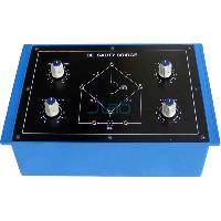
De Sauty Bridge
Product Code : EL-AET-1463
To study the working of a De Sauty bridge and to compare the capacitance of two capacitors.
View Details